Automated Motorized Total Station (AMTS): Common Issues and How to Correct Them
Specto Technology offers hands-on, in-person training classes on the use of Automated Motorized Total Stations (AMTS) several times a year in our Linden, New Jersey Training Center. These trainings include a troubleshooting section which outlines the common issues that have been experienced with the Automated Total Station and how to correct them. If you have not had the opportunity to attend one of the sessions yet – or if you have attended a training and would like to revisit the information – you can learn some of the basics in our 3-blog series: Automated Motorized Total Stations (AMTS): Common Issues and How to Correct Them. Below is the first of the three blogs.
 Are you using an Automated Motorized Total Station (AMTS) to track the progress or performance of your project design, or to monitor structures that are already in place? If so, you have, no doubt, realized the advantages that remote Total Station survey equipment provides.
Sometimes, however, issues arise with the use of Automated Total Stations. We know that every situation is unique but have found that there are a few common mistakes made when using these advanced land surveying instruments and have some suggestions on how to configure your Automated Motorized Total Station and Software to get the best possible readings in order to prevent damages and ensure safety.
The top issues that our clients have encountered while using this automatic land surveying equipment fall into three categories:
- Poor Geometry
- Inappropriate Reference Location
- Temperature and Refraction Issues
In this blog, we will explore the first issue: Poor Geometry.
Explaining Geometry
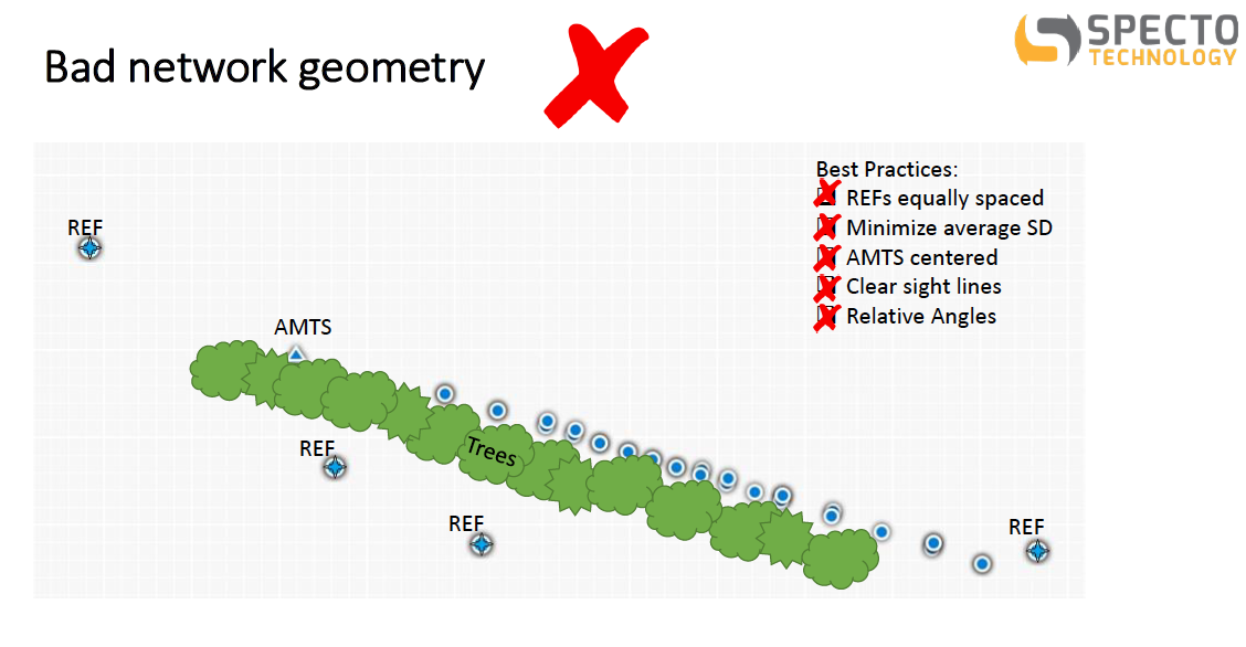
One of the most important things to do correctly when you’re installing Automatic Total Station Survey Equipment is to have a good geometry on your set up. “Geometry” refers to the layout of your single Total Station or your multiple-station network (if you have multiple Automated Total Stations), the layout of reference prisms (stable points which enable your Total Station equipment to determine where they are located in space), and the position of your monitoring target relative to your Total Stations.
Spacing Out Your Reference Points
When it comes to the number of prisms you have, a general rule is: more is better. Ideally, you want to have at least three (3) reference prisms.
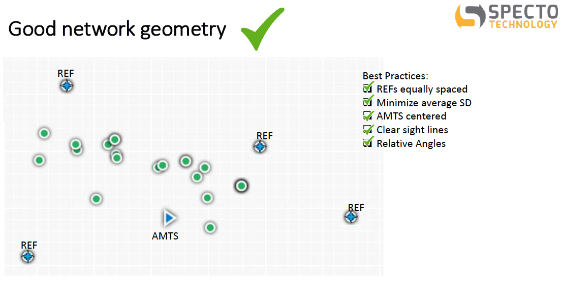
When setting up your network, your Total Station survey instrument should be at the center of your network with your reference prisms equally distributed around it with similar angles between them and the station.
For example, if you had three reference prisms you would want them to be 120 degrees apart from each other. Your automated motorized Total Station would sit at the center with a 120-degree angle between each pair of reference prisms and the Total Station equipment.
Next, you need to minimize the range of slope distances from your automatic Total Station to all your monitoring prisms. Slope Distance is the shortest line distance between the Total Station and any prism. You will get more errors on shots that are farther away than on ones that are closer, so you want your prisms as close as possible to the Total Station while still being outside the zone of influence of whatever you are monitoring.
Also, you don’t want to have some prisms incredibly close and others that are far away; this will negatively affect the accuracy of the measurements.
Of course, this is the ideal setup. However, in real-world situations, it is often not possible to have an ideal setup.
For example, if you’re excavating a construction site and your automated motorized Total Station has to be somewhere where it can see the inside of the excavation and buildings above ground, you obviously won’t be able to just float your Total Station in the air above the middle of the excavation.
So, taking the real-life factors into account, you want to get as close to the ideal as possible; with your Total Station equipment as close to the center as possible and your reference prisms as equally distributed as possible at the least possible slope.
Ensure Clear Sight Lines
The next point is to make sure that your network geometry allows for clear site lines between your Automated Total Stations and your prisms. To state the obvious, if it can’t see it, it can’t measure it.
It is important to make sure that the Automated Motorized Total Station can actually:
- See ALL of your prisms;
- See your prisms WELL; and
- See your prisms REPEATEDLY.
For example, if there are parking spaces where you know cars or work vehicles are going to be parked periodically throughout the day between your Automated Total Station and some of your prisms, those “blocked” prisms will not be read all the time. In this case, you need to make sure the prisms are positioned so that parked vehicles will not block the sight line between the prisms and the Total Station instrument.
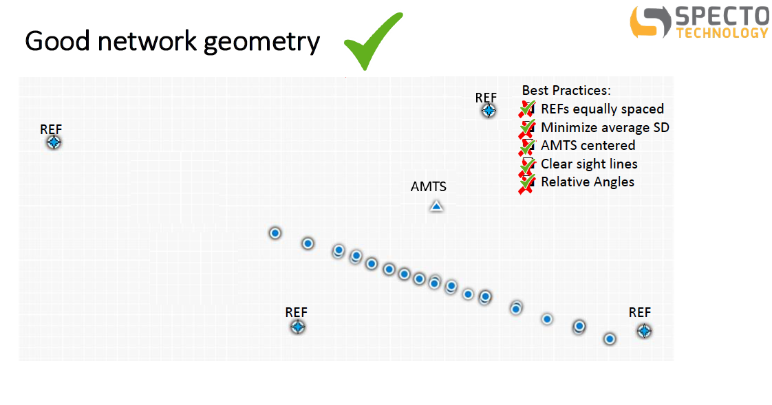
Use a Wide Range of Horizontal Angles
By placing your prisms with a wide range of horizontal angles from the Total Station land surveying equipment, you can avoid duplicate reading of the same point. Even though the prisms themselves might be twenty feet from each other, you want to avoid having prisms that, from the Total Station’s point of view, are only a couple of fractions of arc degree away from each other.
Think of it like this: if you were to draw a circle around the Total Station and measure the angle along the arc of that circle where the Total Station had to turn to point towards every prism it’s monitoring, you want those points to be spread out as much as possible around that circle. This lessens the chance that, during a normal monitoring cycle, the Automated Total Station turns to measure a point that it read yesterday and it’s still pointing at the exact same point that it was, and not at a point that is within the Total Station field of view half of a degree to the left.
For example, a worst case scenario for this sort of situation is one that comes up very commonly when monitoring a railway or a road. If you have prisms that are lined up along the alignment of the road or the railway and then your Total Station is installed some number of feet back along the road or the railway in the same direction that all the prisms are going, when your Total Station turns to look at those prisms there’s just one direction that the Total Station is pointing. The Total Station is down the road to the west, then it’s looking east plus or minus one or two degrees to measure every single prism. In this situation, it is very easy for the Total Station to pick up the wrong prism. The result is either bad data, no data (if you’re filtering the data properly), or false alarms.
If you have followed the other suggestions above, the correct angles should already be in place. If your automated motorized Total Station is centered with all the rest of your prisms spread around it, you’ll already have a wide range of angles.
 Software Cannot Fix Bad Geometry
If you have laid out your network poorly or installed your Automated Total Station in a way that doesn’t allow it to read sufficiently high-quality reference points, there’s no amount of magical software that can fix your data and turn bad data into good data. It’s like the old coding idiom, “garbage in, garbage out.” If you’re not measuring good data, you can’t get good results. Even if you’re using a network adjustment software, which helps get the best out of the data that you have recorded, it can’t make bad measurements good.