Overview
Using an Automated Motorized Total Station (AMTS) to track the progress or performance of a project design, or to monitor structures that are already in place, has many advantages… as long as the equipment is set up and positioned correctly. There are a few common issues, however, that tend to arise with the use of this type of automated land surveying equipment. These issues can typically be minimized or prevented by adhering to a few basic configuration guidelines for both the AMTS and its associated software. To get the best possible readings from the equipment and, in turn, prevent damages and en
sure safety at the project site, operators need to pay close attention to three key issues – Optimizing Geometry; Mapping & Stabilizing Reference Prisms; and Minimizing Temperature & Refraction Issues. All of which will be covered in this article.
Optimizing Geometry
One of the most important factors when installing a remote Total Station is to ensure good geometry during design and set up. “Geometry” refers to the layout of the Total Stations, reference prisms and the prisms being monitored.
References prisms are stable points which enable the AMTS to determine where it is located in space. The AMTS measures the reference prisms and then records their original locations to use as a reference.
A. Spacing Out Your Reference Points
When it comes to the number of prisms used as reference points, a general rule is: more is better.
When setting up the network, a minimum of three (3) reference prisms is required. The AMTS unit should be located at the center of the network, with the reference prisms equally distributed around the unit at similar angles. The distance between your reference prisms and your Total Station can be varied, but most importantly, references should be located outside of the zone of influence of whatever you want to monitor. In addition, you should always have at least one reference that is farther from your AMTS than the farthest monitoring prism.
Having monitoring prisms that are located farther from your AMTS than your farthest reference is called monitoring outside of your network and should not be done.
The range of slope distances from your Total Station to all of your monitoring prisms needs to be minimized. “Slope distance” refers to the shortest distance between the Total Station and any prism. The farther away that the prisms are from the Total Station, the larger the measurement error will be. The accuracy of the instrument is measured as a fixed base accuracy plus a part per million distance. For example, the Topcon MS05AXII half- second instrument has an accuracy of 0.5 mm + 1 ppm. That means it’s always better to try to limit the distance to your monitoring points.
For example, in a network that has three reference prisms, ideally, the AMTS unit should be located at the center of the network with 120-degree angles between each prism.
Of course, this is the ideal setup. In real-world situations, it is often not possible to have an ideal setup. For example, if you are excavating a construction site that requires your Total Station to see the inside of the excavation as well as the buildings above ground, it’s sometimes very difficult to position your Automated Total Station in a place where it can see both areas.
In summary, when setting up a network, it is important to get as close to the ideal as possible. After taking real- life factors into account, the Total Station should be as close to the center of the network as possible and the reference prisms should be equally distributed.
B. Ensuring Clear Sight Lines/Avoiding Obstructions
In addition to ensuring that reference prisms are spaced out correctly, the network geometry must allow for clear site lines between the AMTS unit(s) and the reference prisms. To state the obvious, if it can’t see it, it can’t measure it!
It is important to make sure that the Total Station(s) can:
- See ALL of the prisms;
- See the prisms WELL; and See
- the prisms REPEATEDLY.
REAL-WORLD EXAMPLE
If there is an area in which cars or work vehicles are parked periodically throughout the day between the Total Station(s) and some of the reference prisms, those “blocked” prisms will not be read all of the time. In this scenario, it is imperative to ensure that the prisms are positioned such that the parked vehicles will not block the sight line between the prisms and the Total Station unit(s).If a prism is placed in a location where it might be “blocked” from the sight line of the Total Station unit(s), it will have the same effect as a damaged prism or one that has been removed altogether from the network. That is, the particular reference point for the blocked or obstructed prism will be removed from the Total Station’s calculations and thus, will result in “jumps” in the data.
If there is an area in which cars or work vehicles are parked periodically throughout the day between the Total Station(s) and some of the reference prisms, those “blocked” prisms will not be read all of the time. In this scenario, it is imperative to ensure that the prisms are positioned such that the parked vehicles will not block the sight line between the prisms and the Total Station unit(s).If a prism is placed in a location where it might be “blocked” from the sight line of the Total Station unit(s), it will have the same effect as a damaged prism or one that has been removed altogether from the network. That is, the particular reference point for the blocked or obstructed prism will be removed from the Total Station’s calculations and thus, will result in “jumps” in the data.
C. Utilizing a Wide Range of Horizontal Angles
By locating your prisms with a wide range of horizontal angles from the Total Station you can limit the chances of reading the wrong prism. Regardless of the distance between two points, it is important to avoid having prisms that, from the Total Station’s field of view, have a very small difference in their angular coordinates.
The Total Station uses Automatic Target Recognition (ATR) to track where a prism is currently located each time it reads the prism. This ATR looks for the prism within the parameters of a search window. If, for example, the initial search window of 0.015 DMS (Degrees, Minutes, Seconds), is not able to locate the prism, it will expand the search window up to a full arc degree or more until it can locate a prism.
If the relative angle of two prisms is less than the search window that is needed to locate the prisms, the wrong prism will often be located during the ATR. The impact of this can be lessened through the use of filters such as a Slope Distance Filter or 3D Coordinate Filter which can be configured to reject a reading if the filter has changed by more than a predefined amount.
A Total Station also has a built-in Prism Check feature. This feature uses the prism type selected and the slope distance measured to determine if the point measured is correct to the type of prism. Both of these options can invalidate readings and prevent false alarms being triggered by a misread prism, but will still result in a loss of data. A better solution is to avoid the situation through better geometry.
REAL-WORLD EXAMPLE
A worst case scenario for this sort of situation is one that comes up very commonly when monitoring a railway or a road. If the monitoring prisms are located along the road or railway and the Total Station is not set well back from the road/railway at a perpendicular angle, it is very easy for the Total Station to pick up the wrong prism. The result is either bad data, no data (if you’re filtering the data properly), or false alarms (if you aren’t).
A worst case scenario for this sort of situation is one that comes up very commonly when monitoring a railway or a road. If the monitoring prisms are located along the road or railway and the Total Station is not set well back from the road/railway at a perpendicular angle, it is very easy for the Total Station to pick up the wrong prism. The result is either bad data, no data (if you’re filtering the data properly), or false alarms (if you aren’t).
It is important to note that software cannot fix bad geometry!
If the network has been laid out poorly or the Total Station(s) has been installed in a manner that doesn’t allow it to read a sufficient number of high-quality reference points, there’s no amount of magical software that can fix the data – or turn bad data into good data. It’s like the old coding idiom, “garbage in, garbage out.”
Even if a network adjustment software (which helps get the best out of the data that you have recorded) is being used, it can’t make bad measurements good.
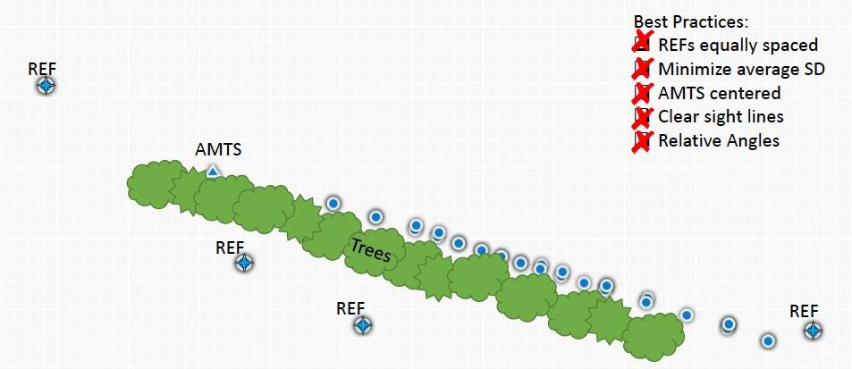
Below is an example of poor setup in terms of geometry.

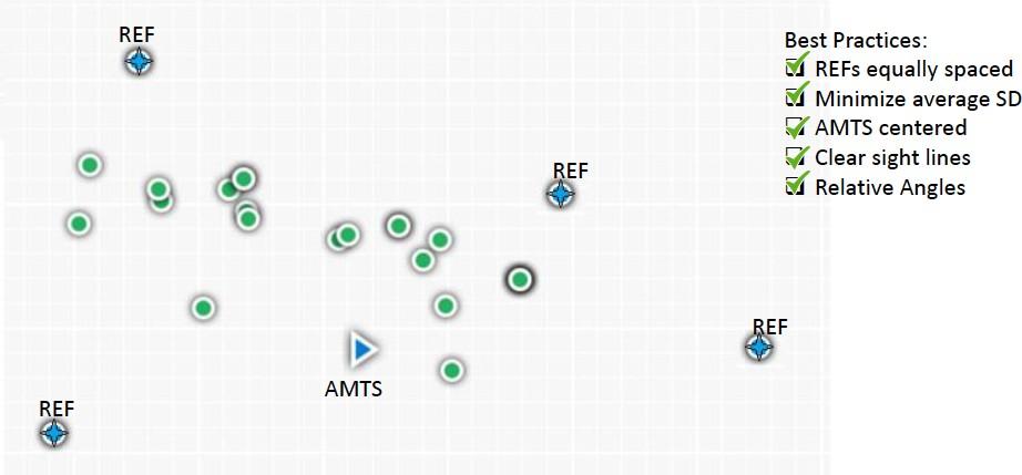
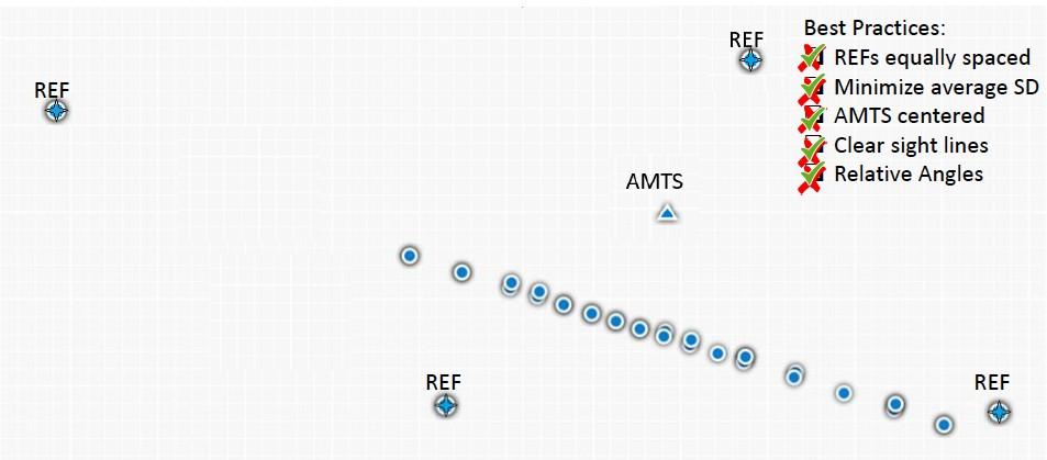
The following two examples show optimal network geometry.

Mapping and Stabilizing Reference Prisms
The Total Station calculates its position based on where it measures the reference prisms to be at any given time. This is called “resectioning.” (This is all based on geometry, trigonometry and a process called the Helmert Transformation.1) The AMTS assumes that the prism is still at the original location, then calculates where it is relative to that prism.
Figure 1: Resection
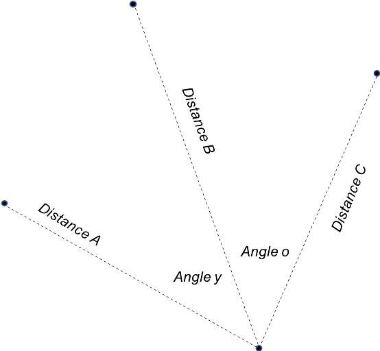
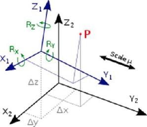
Figure 2: Helmert Transformation
Reference prisms allow the Total Station to correct itself for any drift in the instrument. Drift can be caused by internal variations in the Total Station or from environmental changes at the location where the AMTS unit is located (e.g., temperature changes or pressure changes). Because the reference prisms are the basis for all measurements by an AMTS, it is vitally important for them to be stable throughout the life of the monitoring program.
A. Choosing a Stable Structure
As noted previously, reference prisms should always be installed in locations where they will be stable; making sure that they are well out of the zone of influence of the construction activity.
REAL-WORLD EXAMPLE
When using a Total Station to monitor an excavation site, you do not want to install reference prisms on a wall directly adjacent to the excavation. Reference prisms typically need to be at least a hundred feet from the zone of influence so you do not resection based on the movement caused by the construction.
When using a Total Station to monitor an excavation site, you do not want to install reference prisms on a wall directly adjacent to the excavation. Reference prisms typically need to be at least a hundred feet from the zone of influence so you do not resection based on the movement caused by the construction.
In addition to taking the construction activity that is being monitored into consideration, to ensure physical stability of the reference prisms, consideration must also be given to the physical properties of the surface on which the prism is being installed or mounted.
For example, a reference prism should never be installed on temporary scaffolding or any kind of structure that might be likely to move on its own outside of influence from the construction activity.
A general rule of thumb is: the larger or more massive the structure, the better it is for using as a reference location. We must, however, also look at other outside influences on the stability of the prisms. If the surface on which a prism is mounted is susceptible to movement from wind or, perhaps, thermal effects on the surface (e.g., sun exposure on a metal surface), the stability of the prism can be negatively impacted. Taking this into consideration, shady spots are generally better than those that have high sun exposure.
REAL-WORLD EXAMPLE
If a prism is mounted on a billboard that is on the top of a building, consideration must be given to the wind blowing on that large surface area of the billboard. The wind can cause the billboard to move and, in turn, create instability for the prism. Or, if a prism is on a structure made of metal, daily sun exposure can affect the position of the prism.
If a prism is mounted on a billboard that is on the top of a building, consideration must be given to the wind blowing on that large surface area of the billboard. The wind can cause the billboard to move and, in turn, create instability for the prism. Or, if a prism is on a structure made of metal, daily sun exposure can affect the position of the prism.
B. Avoiding Other Influences that Cause Instability
Once a stable structure on which to install reference prisms is chosen, consideration must be given to other external influences that can affect the way the prisms are read. Reference prisms need to be protected from potential damage from traffic or anything else that can cause them to be moved or knocked off of the structure on which they are mounted.
When a reference prism is removed or added to a Total Station network, it will change the adjustment made to the unit’s position and cause all of the data in that network to shift. Therefore, if one or more of the prisms are damaged or destroyed, jumps in the data will occur due to the prism being removed from the calculations. Naturally, this is something that needs to be avoided.
Minimizing Temperature and Refraction Issues
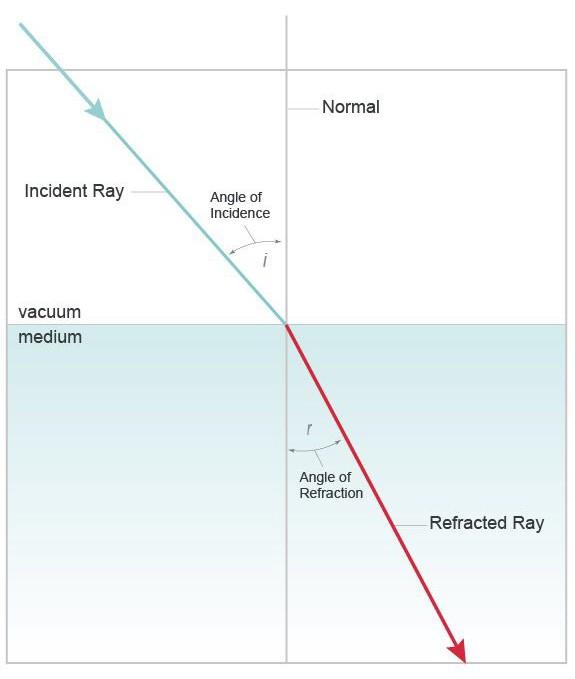
Merriam-Webster defines refraction as the deflection from a straight path undergone by a light ray or a wave of energy in passing obliquely from one medium (as air) into another (as water or glass) in which its velocity is different.2
For our purposes, when a land surveying instrument like a Total Station has to “shoot” its laser through something that changes the refractive index of the air, refraction occurs and measurements are impacted. Refraction can be caused by atmospheric effects or by other “meshes” that add noise to the signal and bend light, causing fluctuations in the data being transmitted from the prisms to the Total Station.
Figure 3: Refractive Index (RI)
A.The Weather’s Effect on Measurement
When it comes to weather, temperature has the greatest atmospheric effect on monitoring. Temperature effects will show up in a variety of different ways in data from an AMTS unit. One of the most direct ways that temperature influences readings is from actual movement of a structure that is caused by heating and cooling effects throughout the day, or even through seasons. As things heat up, they expand and as they cool down, they contract. This expansion and contraction causes buildings and structures to move and shift daily and seasonally. These movements or shifts show up in AMTS data. In a perfect world, we would be able to control the effects of temperature on the data collected by surveying instruments, but we do not live in a perfect world. Since monitoring occurs over a period of time, these fluctuations are unavoidable and are going to affect measurements. Therefore, it is vitally important to understand how these daily or seasonal effects alter the data.
Another more subtle type of influence that atmospheric effects have on the collected data is changes to the air through which the measurements are being made. So as temperature, pressure and humidity change, the refractive coefficient of the air through which the equipment is measuring changes as well. This shows up as small changes in measurements throughout the days or months and can be corrected by using what is known as a Parts Per Million (PPM) correction. A PPM correction can automatically be applied when using a Total Station with an atmospheric sensor. In a typical manual survey, temperature, humidity and barometric pressure are entered into the Total Station prior to running measurements for the day. The same process can be done automatically for an AMTS with an atmospheric sensor (like the Auto-Meteo) that is integrated into the AMTS hardware and software.
B. Heat Shimmer and Shading of the Total Station
There can also be more localized temperature effects or refractions caused by heat. Heat shimmer is an optical phenomenon brought on by air rising above a hot surface, such as asphalt, that bends the light. When asphalt is heated by the sun, the air nearest to the road becomes hotter than the air above the road. That hot air bends light. When the hot air rises, it creates a blurry, mirage-like effect, or shimmer, that distorts the details of the landscape around it.
REAL-WORLD EXAMPLE
Another example of heat shimmer is warm air that is being emitted from an exhaust vent on a building. When a Total Station has to shoot through that sort of “mesh” to get to a reference prism, refraction will occur. The refraction will then show up as noise in the measurement of that particular reference prism and, consequently, propagate itself as noise in the calculation of where the Total Station equipment is, and thus transfer errors to the monitoring data collected. This type of localized refraction has a significant impact on the data being collected and cannot be corrected by an atmospheric sensor because it occurs in a very localized area. In order to lessen the impact, the Total Station network should be set up in a way that avoids heat shimmer.
Another example of heat shimmer is warm air that is being emitted from an exhaust vent on a building. When a Total Station has to shoot through that sort of “mesh” to get to a reference prism, refraction will occur. The refraction will then show up as noise in the measurement of that particular reference prism and, consequently, propagate itself as noise in the calculation of where the Total Station equipment is, and thus transfer errors to the monitoring data collected. This type of localized refraction has a significant impact on the data being collected and cannot be corrected by an atmospheric sensor because it occurs in a very localized area. In order to lessen the impact, the Total Station network should be set up in a way that avoids heat shimmer.
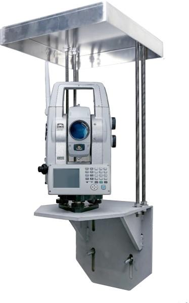 There can also be thermal effects on the AMTS unit itself, or the structure on which the Total Station is mounted. These thermal effects can cause localized movement of the structure. This is sometimes a big problem, sometimes not. It can be corrected as long as the network has stable reference locations (as explained earlier in this paper).One issue which cannot be corrected with stable reference locations is the effect of direct sunlight. If the sun is beating down directly into the scope of the AMTS, the light floods the sensor and adds a lot of noise into the signal that the Station is measuring from the reference prism. This will have a definite impact on the measurements. To avoid this issue, it is always good to have a solar shield or roof installed above the Total Station in order to reduce the amount of direct sunlight on the Total Station throughout the day.C. Other Sources of Refraction to Consider
There are other sources of refraction to consider such as leaves, a chain link fence or even one of those little orange construction fences. When the light signal from the AMTS goes through these “meshes,” it will be refracted so the measurement will not be as accurate as it would be without these diversions. The same can happen if the reference prism is partially obstructed by the edge of another object. When the light has to go around an object, the light bends and impacts the data.
To summarize, the key takeaways with respect temperature and refraction are:
- Avoid sources of refraction (whether they be meshes or temperature effects);
- Avoid positioning the Total Station sight directly across from heat sources;
- Correct for temperature, humidity and barometric pressure with an atmospheric sensor;
- Physically protect the AMTS by installing a shade; and
- Try to install reference prisms in the shade, or someplace less likely to be affected by the sun on a daily basis.
Conclusion
An Automated Motorized Total Station can provide the data needed to effectively monitor the ground or structures adjacent to construction activity. To collect the most accurate data possible, it is important to configure the monitoring network optimally. Once several locations for reference prisms have been identified, it must be determined whether those locations make sense for the network that is being configured. You must ensure that your reference prisms are equally distributed around the Total Station, avoid instability and obstructions, and eliminate sources of refraction, such as weather and other meshes. By adhering to these basic configuration guidelines, damages can be prevented and your project will be a success!
References:
1 The Helmert transformation (named after Friedrich Robert Helmert, 1843–1917) is a transformation method within a three-dimensional space. It is frequently used in geodesy to produce distortion-free transformations from one datum to another. (Source: Wikipedia https://en.wikipedia.org/wiki/ Helmert_transformation)