
Noise Academy
Sound Waves
A sound wave is a mechanical disturbance that propagates through an
elastic medium, transferring energy through changing pressure and particle motion.
elastic medium, transferring energy through changing pressure and particle motion.
ON THIS PAGE
In air, the molecules themselves do not travel from the source to the receiver. Instead, they oscillate about their equilibrium positions while the disturbance moves through the medium.
That simple idea underpins almost everything measured in acoustics. A sound level meter detects changing acoustic pressure and derives quantities such as sound pressure level, Leq, peak level and frequency content from that signal.
Understanding how the wave propagates also explains why microphone position matters, why sound behaves differently at different frequencies, and why distance, barriers, buildings and weather can change the level measured at a receiver.
For the distinction between physical sound and when it becomes unwanted noise, see What Is Noise?
Compression, Rarefaction and Longitudinal Motion
A vibrating surface — such as a loudspeaker cone, machine casing or vocal fold — alternately pushes into the surrounding air and pulls away from it.
When it pushes forward, nearby air molecules are compressed slightly, creating a region of elevated pressure called a compression.
When the surface moves back, it creates a region of slightly reduced pressure called a rarefaction.
Each pressure disturbance acts on the air next to it, so the pattern propagates away from the source.
The individual particles move back and forth primarily in the same direction that the acoustic wave travels. Sound in air is therefore described as a longitudinal wave.

Ordinary acoustic waves in fluids such as air and water are predominantly longitudinal because fluids do not support the same bulk shear stresses as solids.
Solids are more complicated. They can support:
- longitudinal waves
- transverse or shear waves
- surface waves at boundaries
That is one reason airborne sound and structure-borne vibration behave differently and are often analyzed using different methods.
The pressure variation involved can be extremely small compared with atmospheric pressure.
20 µPa
The standard reference pressure for sound pressure level is 20 µPa. This is approximately one five-billionth of normal atmospheric pressure.
Twenty micropascals should not, however, be treated as a universal threshold of hearing. It is the standardized reference used to calculate sound pressure level.
For more on that relationship, see Sound Measurements: Sound Pressure, Sound Power and Decibels.
Frequency, Wavelength and Speed
Three fundamental quantities describe a propagating acoustic wave:
- Frequency: how many cycles occur each second
- Wavelength: the physical distance occupied by one cycle
- Wave speed: how quickly the disturbance propagates through the medium.
They are related by:
λ = c / f
where:
λ = wavelength in meters
c = speed of sound in meters per second
f = frequency in hertz
At approximately 20°C, the speed of sound in air is about 343 m/s, or 1,125 ft/s.
This means that wavelength decreases as frequency increases.
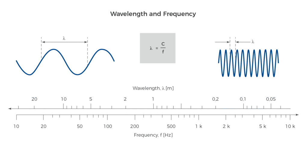
Approximate Wavelengths in Air
| Frequency | Approx. wavelength | US equivalent | Illustrative implication |
|---|---|---|---|
| 20 Hz | 17.2 m | 56 ft | Very long wavelength; conventional barriers can be difficult to make effective |
| 31.5 Hzz | 10.9 m | 36 ft | Typical low-frequency industrial/environmental range |
| 63 Hz | 5.45 m | 18 ft | Diffraction and building response can become important |
| 125 Hz | 2.74 m | 9 ft | Comparable with dimensions of many rooms; modal effects may matter |
| 250 Hz | 1.37 m | 4.5 ft | Barrier geometry becomes increasingly influential |
| 500 Hz | 0.69 m | 2.3 ft | Mid-frequency machinery and speech content |
| 1 kHz | 0.34 m | 13.5 in | Common acoustic reference frequency |
| 4 kHz | 0.086 m | 3.4 in | Short wavelength; obstacles can produce stronger acoustic shadowing |
| 16 kHz | 0.021 m | 0.8 in | Atmospheric absorption becomes increasingly significant |
These examples are useful for understanding field behavior, but frequency alone does not determine what will happen at a particular site.
Barrier dimensions, source and receiver height, path difference, material properties, source directivity and the surrounding environment all matter.
For example, low-frequency sound generally diffracts more readily around obstacles because its wavelength is large relative to many common barriers.
That does not mean low-frequency sound simply passes through or around every barrier without attenuation. Properly designed barriers, enclosures and building elements can still provide low-frequency control, but they usually require more favorable geometry or greater mass and dimension than equivalent high-frequency controls.
The relationship between frequency and acoustic measurement is covered in more detail in Sound Frequency.
The Speed of Sound in Air Depends on Temperature
The speed of sound depends on the properties of the medium.
For dry air over typical environmental temperatures, a useful approximation is:
c ≈ 331.3 + 0.606T
where:
T = air temperature in °C
c = speed of sound in m/s
| Temperature | Approx. speed | Approx. speed |
|---|---|---|
| −20°C / −4°F | 319 m/s | 1,047 ft/s |
| 0°C / 32°FF | 331 m/s | 1,087 ft/s |
| 10°C / 50°F | 337 m/s | 1,106 ft/s |
| 20°C / 68°F | 343 m/s | 1,125 ft/s |
| 30°C / 86°F | 349 m/s | 1,145 ft/s |
| 50°C / 122°F | 362 m/s | 1,188 ft/s |
| 60°C / 140°F | 368 m/s | 1,207 ft/s |
The SV 307A has an environmental operating temperature range of −20°C to +60°C.
Why Temperature Matters Outdoors
Temperature affects more than the wave speed itself.
Vertical temperature gradients can refract sound.
Depending on how temperature varies with height, sound can bend either toward or away from a receiver.
Wind gradients can create a similar directional effect because wind speed typically changes with height.
As a result, long-range sound levels can differ substantially between different meteorological conditions even when the source itself has not changed.
For example, atmospheric conditions may:
- refract sound toward the ground
- change propagation differently upwind and downwind
- refract it upward and create a relative acoustic shadow
- alter which receiver locations are most affected

This is one reason meteorological data can be valuable during long-term environmental monitoring.
The SV 307A can store meteorological measurements such as wind speed, direction, rainfall and humidity alongside noise data when a compatible external weather sensor is connected.
Whether weather monitoring is required depends on the applicable standard, permit, monitoring plan and purpose of the measurement.
Humidity and atmospheric pressure generally have smaller effects on the speed of sound than temperature under normal outdoor conditions.
Humidity is particularly important in another way: atmospheric absorption of sound is frequency dependent and can substantially affect high-frequency propagation over longer distances.
Near Field, Far Field and Microphone Position
The acoustic field immediately around a source can be complex.
Different parts of a machine may radiate at different amplitudes and phases, and pressure can change rapidly over relatively small distances.
This region is commonly described as the near field.
Near-field measurements are not inherently wrong.
They can be entirely appropriate when a test method specifically requires measurement close to machinery, when investigating individual components, or when evaluating worker exposure at a defined operating position.
The important limitation is that simple far-field spreading relationships should not automatically be used to extrapolate near-field measurements.
Small movements of the microphone can produce relatively large changes close to a complex source.
Moving Toward the Far Field
Farther from a sufficiently compact source, the acoustic field may increasingly behave like a propagating far field.
The relationship between sound level and distance then becomes more predictable.
A commonly used practical rule of thumb places the transition toward far-field behavior at approximately one wavelength of the lowest frequency of interest, but this is not a universal boundary.
Actual behavior depends on:
- source dimensions
- source directivity
- frequency
- reflections
- measurement geometry
- the applicable test method
A large machine should not automatically be treated as a point source simply because the microphone is several meters away.
The purpose of defining near and far fields is therefore not to declare one region “valid” and the other “invalid.”
It is to understand which acoustic relationships can reasonably be applied to the measurement.

Free Field, Diffuse Field and Pressure Field
Acoustics also uses several idealized descriptions of how sound arrives at a microphone.
| Field type | Description | Typical example | Measurement implication |
|---|---|---|---|
| Free field | Direct sound dominates with no significant reflections | Anechoic chamber; sufficiently open outdoor environment | Directional/free-field microphone response matters |
| Diffuse or reverberant field | Sound arrives from many directions and reflections are significant | Reverberation chamber; highly reflective room | Random-incidence response becomes important |
| Pressure field | Sound pressure is approximately uniform in magnitude and phase over the sensing region | Acoustic coupler, small cavity, calibration fixture | Pressure-response characteristics apply |

These are idealized field descriptions.
Real industrial, building and environmental acoustic fields frequently contain a mixture of direct and reflected sound.
An outdoor site, for example, may approximate free-field conditions in some directions while still being influenced by the ground, nearby façades, equipment and temporary structures.
The Instrument Can Affect the Field
At higher frequencies, the physical dimensions of the microphone, windscreen and instrument housing become increasingly significant compared with wavelength.
The equipment itself can therefore affect the acoustic field through reflection and diffraction.
Professional sound-measurement systems account for directional response through their microphone design and, in some cases, configurable compensation.
The SV 307A provides manufacturer-defined compensation settings for different acoustic incidence conditions.
Its manual identifies:
Environment compensation for an acoustic signal parallel to the microphone grid, and
Airport compensation for a signal perpendicular to the microphone grid.
The correct setting should therefore be selected according to the installation and manufacturer instructions.
Using the wrong directional compensation can introduce a systematic frequency-dependent difference that additional averaging will not remove.
The Inverse-Square Law: About 6 dB per Doubling of Distance
For an ideal point source radiating into a free field, the acoustic energy spreads over an increasingly large spherical area as distance increases.
Sound pressure decreases approximately in proportion to 1/r.
The corresponding sound-pressure-level relationship is:
L₂ = L₁ − 20 log₁₀(r₂ / r₁)
where:
L₁ = level at distance r₁
L₂ = level at distance r₂
If the distance doubles
r₂ = 2r₁
then
L₂ ≈ L₁ − 6 dB
So under ideal conditions
10 m → 20 m ≈ −6 dB
20 m → 40 m ≈ −6 dB
This is the familiar 6 dB per doubling of distance rule.
But the conditions matter.
The approximation assumes:
- a sufficiently compact source
- free-field propagation
- no major screening or additional sources
- far-field behavior
- negligible significant reflections
- stable source emission
It is therefore a useful starting point, not a universal site-prediction formula.
What About Line Sources?
An ideal infinite line source spreads energy cylindrically rather than spherically.
Its level decreases by approximately 3 dB per doubling of distance.
Long transportation corridors can sometimes approximate line-source behavior over particular geometries and distance ranges.
A real highway, however, consists of finite, moving sources. It does not behave as a perfect infinite line source under every condition.
Detailed transportation-noise models account for much more than a simple 3 dB distance rule.
Why Real Measurements Often Differ
Geometric spreading is only one part of outdoor sound propagation.
Measured levels can also be affected by:
- source directivity
- reflections from buildings and ground
- ground interference
- barriers and terrain;
- atmospheric absorption
- temperature and wind gradients
- source dimensions
- additional sound sources
- background sound.
Meteorological refraction does not eliminate geometric spreading or atmospheric absorption. It can, however, change the propagation path and produce higher or lower levels at a particular receiver than a simple free-field calculation would predict.
Indoors, the inverse-square relationship can also break down once reflected sound becomes a major part of the acoustic field.
Beyond the room’s critical distance, the reverberant component may dominate and moving farther from the source may produce much less reduction than the free-field 6 dB rule suggests.
The important lesson is:
Distance matters, but distance alone does not determine environmental sound level.
For measurement planning and interpretation, the source, propagation path, receiver and surrounding acoustic environment all need to be considered.
The Practical Takeaway
A sound wave is a moving acoustic disturbance, but its behavior depends strongly on frequency, wavelength, source geometry, distance and the environment through which it travels.
Several useful field principles follow:
- lower frequencies have longer wavelengths and generally diffract more readily around obstacles
- higher-frequency sound is typically affected more strongly by atmospheric absorption
- the speed of sound changes with temperature
- temperature and wind gradients can refract outdoor sound
- near-field measurements should not automatically be extrapolated using far-field rules
- free, diffuse and pressure fields describe different acoustic conditions
- a point source in ideal free-field conditions loses approximately 6 dB per doubling of distance
These are engineering tools rather than universal laws for every site.
Real environmental monitoring combines the physics of the source and propagation path with documented measurement location, meteorology, instrument configuration and surrounding conditions.
For related topics, see Sound Frequency, Sound Measurements, Noise Monitoring, Background Noise and Residual Sound, Class 1 vs Class 2 Sound Level Meters, and the Specto Noise Academy.
Request Quote
For Sales, Rentals, and Quotes, please get in touch with us by filling out the form below. Our knowledgeable staff is ready and eager to assist you!